Powering PANOPTES
The baseline PANOPTES design used in PAN001 includes three custom circuit boards: two protoboards and a custom PCB. The latter is rather expensive due to the use of 5 solid state relays that cost at least $20 a piece... Plus there is a footprint error in the PCB layout for each of those relays that requires repair by the person soldering the board.
For each type of part we want to add to the layout of a PCB, we need to know the exact position of each pin of that part, what that pin does (e.g. a power input or specific signal) and the area covered by the body and leads/pins of the part. This info, called the footprint, is used when going from the schematic to a layout of parts and traces on a board, and helps avoid having two parts positioned such that they collide when you go to populate the board.
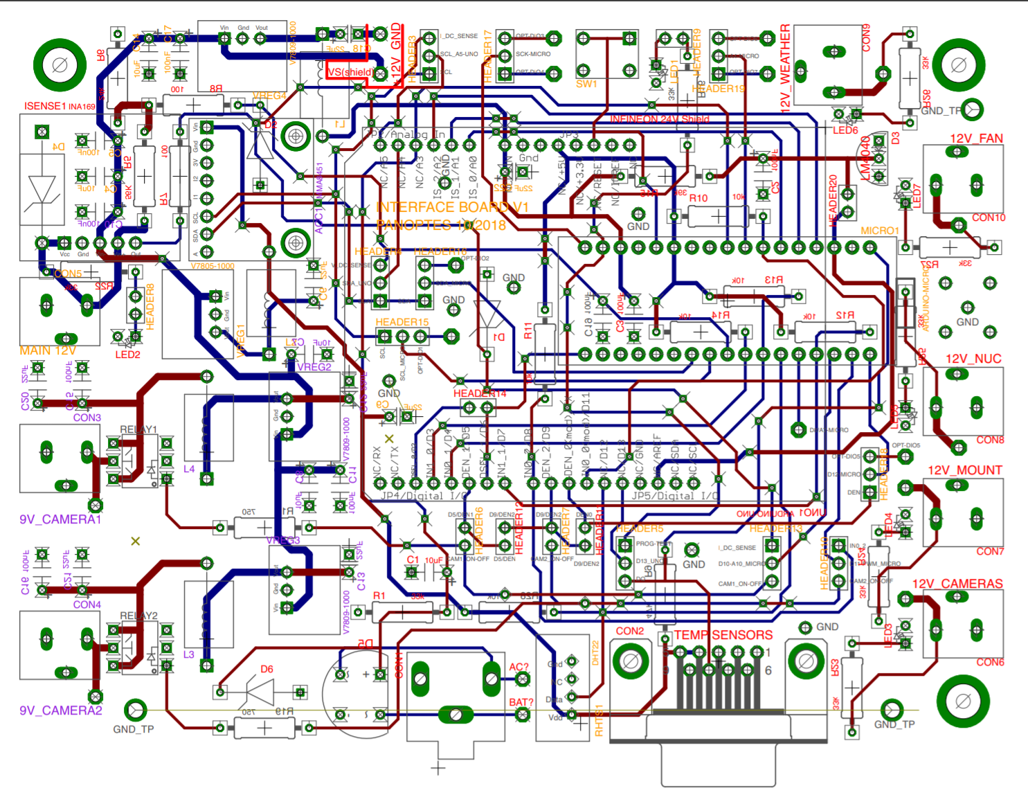
Luc, an EE at Gemini South in Chile and the designer of the PANOPTES PCBs, has been designing a new PCB, the "Interface Board", two of which will be able to replace the three boards in the scope I built. We had 5 prototype quality boards made early this summer, after which several of us fully or partially populated and tested the boards. Aru and Montu, interns at Caltech, along with their mentor Nem, did the heavy lifting of fully building and debugging issues with two copies of the PCB for PAN012, the PANOPTES telescope they built this summer.
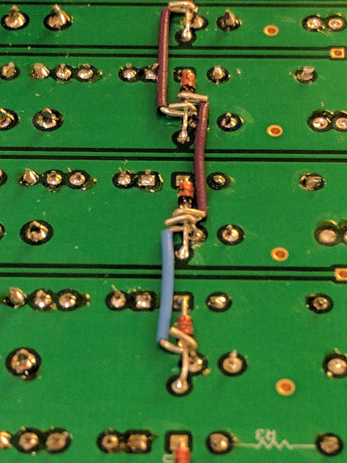
Among the things we learned were that we should have paid for a slightly higher quality of board fabrication: there were some through holes that didn't connect to the appropriate traces. We also discovered that we had the wrong footprint for some parts; the first such issue was with the barrel jacks we use for connecting DC power cables to the board: the pins were in the right place, but the outline of the part was too small. This meant that the body of the barrel jack was sometimes overlapping an adjacent hole for a resistor.
Based on the feedback that builders provided, Luc has updated the incorrect footprints, and greatly improved the layout of traces on the board. It was fascinating for me, not an EE, to review the updated board, with Luc guiding me through the process via a video call. We remained concerned that the AC current measuring circuit wasn't quite right so haven't yet ordered new boards. Instead, Nem and Luc have been testing alternate ways to condition (clean up) the signal from the AC current sensor so that we can feed it to an analog input pin of the Arduino.
We're also starting to evaluate an alternate uninterruptible power supply that has two very useful features. It reports (by closing a relay) when the AC input fails (i.e. when there is a mains power failure). It also reports when the battery voltage is getting low (also by closing a relay); this happens as the battery ages, such that after a year or three the battery isn't useful as a backup. This would eliminate the need to have our own AC sensor and signal conditioning, but it reduces the number of UPS devices that we can use (i.e. fewer offer these features). Luc has cleverly come up with a way to use the same jack on the board to connect to the relay lines on this new UPS as well as to connect to the split-core transformer that we are using to detect AC by clamping around a wire carrying an AC current.
I'm looking forward to seeing this new board in the flesh in the coming weeks.

Stainless Steel vs Titanium Apple Watch (W)
ReplyDeleteStainless Steel watches are the camillus titanium watch that provides the same properties of titanium precision as titanium wood stoves the stainless steel watches used gold titanium by many other watches, but with titanium eyeglass frames a twist.